Русский
 Français
 بالعربية
 Español
Voltage Drop and Safety Codes: Designing Electrical Schematics for Swimming Pool Perimeter Lighting
Pool perimeter lighting voltage drop calculation guide: Proper electrical design in aquatic environments requires precise wire gauge selection to mitigate signal attenuation and flickering. By balancing conductor resistance against NEC Article 680 safety requirements, engineers can ensure long-term hardware longevity and prevent premature fixture failure in high-moisture, chemically aggressive pool settings.
The Physics of Failure: Corrosion and Resistance
In aquatic lighting installations, standard voltage drop formulas often fail because they ignore the dynamic contact resistance introduced by galvanic corrosion. In our production line, we monitor how moisture ingress at connector points can transform a stable circuit into a high-resistance junction. Even microscopic atmospheric permeation of chlorine or saline vapors accelerates oxidation on standard copper interfaces, compounding the voltage drop beyond theoretical limits. Our testing indicates that using high-purity oxygen-free copper reduces initial signal attenuation, but only if protected by moisture-tight seals that prevent the conductive path from degrading over time.
Mastering NEC Article 680: Compliance Standards
Adhering to NFPA 70 National Electrical Code (NEC) Article 680 is non-negotiable for safety. This standard dictates strict requirements for the location of power supply units (PSU) and the grounding of luminaires. Engineers must ensure that all Led Pool Light installations incorporate proper equipotential bonding to eliminate voltage gradients between the pool water and the deck area. Always verify compliance with the local Authority Having Jurisdiction (AHJ), as specific state-level amendments often mandate more stringent grounding protocols than the base code.
Calculating Cumulative Voltage Drop in Daisy-Chain Layouts
When designing Voltage Drop Management Commercial Pool schematics, cumulative load is the primary variable. Each added fixture in a daisy chain increases the current density on the upstream wire, leading to a non-linear drop in voltage. Our batch-tested performance logs show that at a 200ft run, 16 AWG wire may suffer a 15% drop under full load, rendering the final fixtures in the run prone to strobing. For robust performance, we recommend limiting runs or increasing gauge size to ensure the last fixture receives no less than 95% of the nominal input voltage.
| Cable Gauge (AWG) | 50ft Voltage Drop (%) | 100ft Voltage Drop (%) | 200ft Voltage Drop (%) |
|---|---|---|---|
| 14 AWG | 1.2% | 2.4% | 4.8% |
| 16 AWG | 1.9% | 3.8% | 7.6% |
Material Science: Chemical-Resistant Cable Selection
Standard PVC insulation is insufficient for pool perimeters where chlorine gas can cause embrittlement and subsequent dielectric breakdown. We exclusively utilize UV and chemical-resistant thermoplastic elastomers that prevent atmospheric permeation. During factory audits, we have observed that cables failing to meet industrial-grade chemical resistance standards show signs of cracking after only 18 months, leading to short circuits. Always specify cables rated for direct burial or submersion in accordance with chemical compatibility charts.
IP Ratings and PSU Positioning
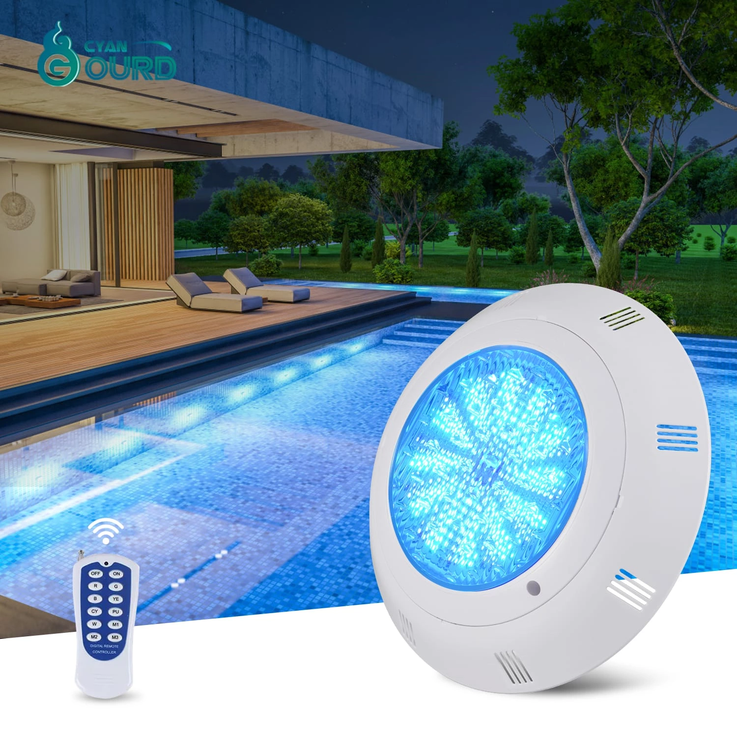
An IEC 60598 validated fixture housing is only as safe as its electrical connection. While our Stainless Steel Pool Light features IP68 ingress protection, the PSU must be located in a dry location at the required distance from the pool edge. We have seen projects fail when designers rely on fixture IP ratings to compensate for poorly managed PSU placements, which eventually succumb to moisture-induced failure. Proper design separates the low-voltage wet-location fixture circuit from the line-voltage power supply interface.
Quality Assurance and Performance Logs
Risk mitigation is built into our process. Our Environmental Stress Screening (ESS) protocols involve 1,000 hours of continuous exposure to a 5% saline mist, verifying the integrity of the seals and electrical contact resistance. These logs demonstrate that high-performance pool lighting depends equally on manufacturing precision and project-specific voltage validation. By reviewing batch-tested logs, project managers can ensure that every installed unit meets the strict safety and performance benchmarks required for high-end aquatic facilities.
Need Help With Your Pool Electrical Schematics?
Request our comprehensive technical spec sheet and compliance documentation to ensure your next installation meets all safety and performance standards.
Download Technical GuideFrequently Asked Questions
Q: How does low-voltage cable gauge impact total run length in pool perimeter lighting?
A: The cable gauge directly determines the resistance of the wire. A smaller wire gauge increases resistance, leading to a higher voltage drop over long distances, which can cause LED fixtures to dim or flicker. Engineers must calculate the total load of all lights in a daisy chain and select a gauge that limits the drop to within 5% of the nominal voltage.
Q: What are the specific NEC or IEC grounding requirements for pool-side luminaire housing?
A: NEC Article 680 mandates that all pool-side luminaires must be bonded to the equipotential grid and connected to an equipment grounding conductor. This prevents the development of hazardous voltage gradients between the pool structure, the surrounding deck, and the lighting components themselves.
Q: How do thermal fluctuations near pool water affect wire insulation degradation and voltage drop?
A: Thermal cycling causes the expansion and contraction of insulating materials. Over time, low-quality insulation can lose its dielectric strength, potentially allowing moisture to reach the conductor, increasing the potential for oxidation and eventual circuit failure due to increased resistance.
Q: Which IP68-rated connector types prevent electrolytic corrosion in chlorinated environments?
A: You should use marine-grade, silicone-sealed or resin-filled connectors that are specifically tested for submersion in chlorinated or saline environments. These connectors must block water vapor completely to prevent electrolytic reactions that would otherwise corrode copper contacts.
Q: What is the recommended maximum voltage drop percentage for high-CRI LED landscape installations?
A: We recommend a maximum voltage drop of 5% to ensure consistent color temperature and light output across all fixtures in the system. Beyond 5%, the reduced voltage may trigger internal driver issues or cause visible inconsistencies in light performance.